
This is a Veteran Owned site
| |
||||||||||||||||||
Installing a Router Lift or Plate
Simple Tools, Perfect FitText & Photos by Tom Hintz Note: The story that follows describes how I install router lift plates. While the procedure works with most router plates (lift or solid plates) I am aware of, be sure to read the instructions that came with your router plate and follow them should they differ from the information presented here. Not following the manufacturer instructions could void the warranty or reduce safety.Table Blank PrepThe router table should be cut to finished size to make laying out the plate location easier. If edge banding
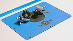
around the table is to be used, installing it before the plate makes it easier to be accurate with front-to-rear measurements that can be important for locating the plate in relation to a miter slot. If applying the surface laminate in your shop rather than using pre-covered material, you have the option of cutting the shoulder hole before installing the laminate. The shoulder hole is not depth sensitive (through hole) and provides an additional path through which to eliminate trapped air from under the laminate during installation. Shoulder HoleMost router lift plates fit in a two-step hole. Commonly a mounting flange approximately ¾"-wide fits into a rabbet around a smaller through hole, sized to accommodate a shoulder that extends downward to the full thickness of the router lift plates. The through hole can be slightly less precise than the rabbet, which must fit the flange closely to locate the plate and prevent it from shifting during use.
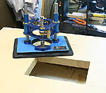
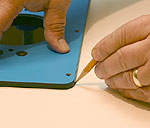
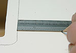
Identify the position of the router lift plate in the table and lay out the shoulder hole. Make sure it is parallel to the front and rear edge of the table. Drill access holes for a jig saw blade in the corners of the layout and then cut the waste out. Set the lift in the hole to be sure it is properly sized and that the plate is parallel to the table edge. Use a rasp to adjust the edges of the shoulder hole if necessary. Lay Out The Flange RabbetSet the plate in the shoulder hole, with its flange flat on the table surface. Carefully adjust its position so it is parallel with the edge of the table, hold it securely and trace its outline onto the table with a sharp pencil. Remove the plate and make sure the layout line is clear all the way around the plate. It is crucial to this process to remember that the INSIDE of this layout line is where the plate fits, not outside of it. All measurements from this point on are taken from the inside edge of the layout line so errors will
tend to make the rabbet slightly undersized, a problem that is easy to remedy. Router plate flanges are commonly ¾" wide but measure yours, it could be different! Using a good quality, sharp ¾", flat-bottomed bit produces a smooth and flat cut. Install the bit and set the depth to 1/16" more than the thickness of the flange. This is important as it provides room to adjust the plate exactly flush with the table surface in the final step of these instructions and later should the need arise. Measure from the cutting edge of the bit to the outside edge of the router base plate to determine the offset. This dimension will be the distance the temporary guide fence will be clamped from the inside edge of the traced layout line. On my router (PC890 series) this dimension is 2 ½" but measure yours! Using a combination square or flat metal rule, measure out from the inside edge of the traced layout line and mark where the edge of the fence is to be. Make at least two widely separated marks along each side of the layout line.
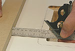
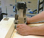
Secure a straight board along the offset marks to act as a guide fence for the router. Snug the clamps down but do not tighten completely. Use a combination square or rule to confirm that the fence is properly set at the offset distance from the inside edge of the layout line. Take your time and get the fence set accurately. With the fence perfectly aligned, secure the clamps so it cannot move during routing. Some router base plates are not exactly round, making it a good practice to keep one spot on the base against the fence for all cuts. I developed a habit of always holding the router handles parallel to the fence, the back edge of the base against the fence. Holding the router like this every time keeps a very small portion of the base against the fence and eliminates any small errors an out-of-round plate or one mounted slightly off center to the base might induce.
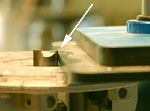
Carefully route one side of the flange at a time, keeping the router against the fence through the entire cut. When the bit approaches the rounded corner you can either freehand it about halfway around the corner or stop when the bit gets to the line and remove any waste the router leaves with a sharp chisel after all sides have been routed. Either way works so use the one that is most comfortable to you. Move the fence to the next side of the flange opening and repeat the process until all four sides are complete. Use a sharp wood chisel to remove any waste material that remains in the corners. Be careful not to remove material into or beyond the layout line. Look the flange opening over to be sure it is free from chips or routing dust that could interfere with the plate when installed. Fitting the PlateSecure the router table top on blocks or between saw horses to allow sufficient height to afford clearance for the lift mechanism when the plate is installed. If adjusting the flange cavity to correct the fit is necessary, make certain the tabletop is secured adequately to prevent it from moving during this process.
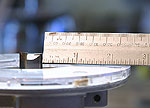
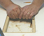
Carefully try to set the plate into the flange cavity. If it fits and rests fully on the bottom of the cavity you are almost done - and either very lucky or exceptionally talented with a router! Most often, the plate will not fit the cavity perfectly the first time. Hold the plate in the cavity as far as it will go and look around it, noting the areas where it is touching the edges of the flange cavity. Sometimes using a sharp pencil to trace along the areas that need trimming makes the process more accurate by confining adjustment work to those points. Remove the plate and using a sharp, flat chisel, scrape the areas interfering with the plate. Remove a small amount of material and try the fit again. Keep in mind that removing very small amounts of material can have a big effect on how the plate fits. If the plate still does not fit, repeat the fit and trim process until it does. Final AdjustmentsMost router lifts (and plates) have a series of leveling screws around their outer edge. Install the screws so they are flush with the bottom of the plate and then place the plate into the cavity. Slowly turn the leveling screws down a little at a time until the plate starts to rise. Adjust the individual screws as needed to get the
plate flush with the router table surface. A good way to check this is to slide a flat piece of wood or plastic with square edges across the table and plate. If the adjustment is not correct you will feel the piece strike the high edge, indicating which way the plate must be adjusted. After adjusting the plate, remove it and put a drop of thin cyanoacrylate glue on the flange surface where the leveling screws contact it. Allow the glue to dry completely before reinstalling the plate. The cyanoacrylate strengthens the MDF, helping it resist the leveling screws digging into it. To keep the plate flush with the surface in the future, the flange recess must be kept free of dust. Get in the habit of cleaning the flange area whenever the plate is removed. A properly fit router lift or plate is crucial to getting the best performance and long life from router bits. A snug-fitting plate also helps eliminate vibration and increases accuracy. See a review of the Rockler FX Lift Plate used in this article. Do you have a comment about this page? - Email Me!
|

All written, photographic and drawn materials are property of and copyright by NewWoodworker.com LLC 2000-2019. Materials may not be used in any way without the written permission of the owner.